Display of Virtual Braille Dots by Lateral Skin Deformation: Feasibility Study
table of contents2. Virtual Braille Display
2.1 Device
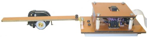
The VBD device consisted of a tactile display mounted on a laterally-moving frictionless slider (see Figure 2) and interfacing control electronics.
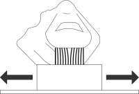
Reading virtual Braille was done by applying the tip of the index finger against the tactile display and sliding it laterally, as shown in Figure 3. When activated, the tactile display caused lateral deformation to the fingertip skin, that could be varied in response to slider movement. The finger remained in contact with the display and dragged it along the reading surface. Although this principle could allow reading with multiple fingers, the width of the display limited the reader to the use of a single finger.
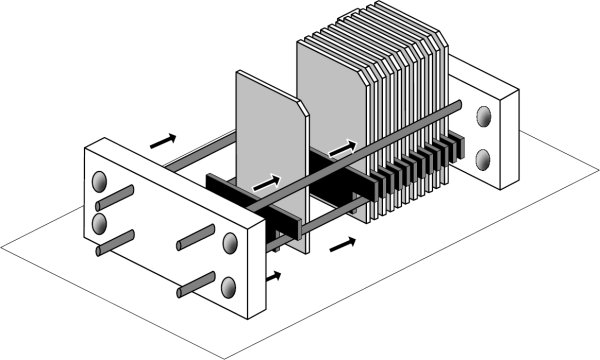
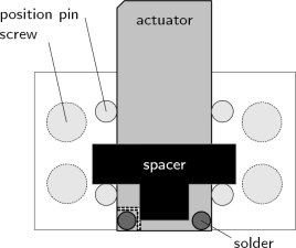
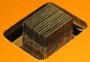
The tactile display was made of a stack of twelve 0.38-mm-thick piezoelectric bender plates (Y-poled, 31.8 mm x 12.7 mm, High Performance Bending Motors from Piezo Systems Inc., part number T215-H4CL-303Y), sandwiched at their base between neoprene spacers and clamped between two rigid end-plates using four locating pins and four screws (see Figures 4(a) and 4(b)). The spacers were cut in a 12-mm-high T-shape so that they rested on the locating pins and allowed room for electrical connections (see Figure 4(b)). Once tightly secured, the spatial period ε, or contactor pitch, was approximately 0.7 mm. This assembly method was selected for the convenience of allowing the design parameters such as thickness, length, shape and material of the actuators and spacers to be changed. In the present study, however, only one configuration was used.
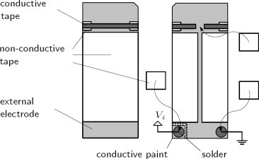
The actuators were driven by a bipolar voltage applied between their central electrode and their two electrically-connected external electrodes. Because of the small space between adjacent plates, the electrodes could not be connected using the methods recommended by the motor supplier. Therefore, the actuators were prepared as shown in Figure 4(c). The external electrodes were joined with adhesive electrically conductive tape (3M Corporation, EMI Copper Foil Shielding Tape 1181) running over non-conductive tape on the sides to prevent shorting with the central electrode. One corner of an external electrode was soldered to a ground wire. The other corner was turned into a small electrode pad (isolated from the rest by grinding off the conductive layer) and connected to the central electrode with conductive paint. A wire used for the control voltage was then soldered to this pad. To prevent contact with the adjacent actuator, the solders were kept significantly thinner than the spacers (0.5 mm) and were protected with non-conductive tape. Traces of conductive paint were applied along the length of the electrodes to improve their reliability (not shown). The actuators were then isolated from the metallic locating pins using non-conductive tape. As illustrated in Figure 3(b), the top corners on one side of the blades were beveled to create a narrow linear array of skin contactors (around 0.2 mm2 in area each). Finally, the tips of the actuators were coated with varnish to isolate them from the skin.
The display could be used by applying the finger either on the large horizontal contact surface or against the surface formed of the beveled corners of the contactors. The latter surface, as shown in Figure 3, provided a narrower contact area more appropriate for the display of dots and was the only one used in this study.
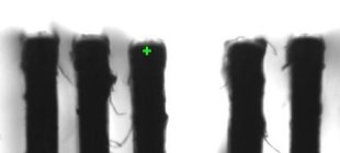
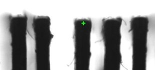
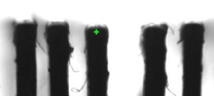
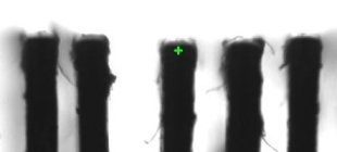
The deflection of the actuator tips was estimated with the help of a camera. Two sample measurements are shown in Figure 5. However, when not loaded by the finger, the deflection range was estimated to be 0.4 mm. As explained in the
next section, the motion was limited in practice to a restricted range of approximately 0.3 mm. The deflection when loaded with the fingerpad could not be quantified but appears to be significantly lower than when unloaded.
The position of the linear slider on which the tactile display was mounted was measured by an optical encoder with a nominal resolution of 17 μm. Interfacing electronics were constructed to permit the refresh of the actuators at 500 Hz according to patterns programmed on a personal computer. This enabled us to program the deflection of each actuator with arbitrary functions of space (see
Section 2.2).
The interfacing electronics, adapted from a previous project, made use of a Field-Programmable Gate Array (FPGA) development board (Constellation-10KE(TM) from Nova Engineering Inc. operating an Altera FLEX 10KE(TM) chip.) with a Universal Serial Bus (USB) 1.1 interface. It was programmed to convert control frames coming from the computer, or "tactile images", into twelve bender voltages by means of 156-kHz pulse-width modulation (PWM). The same, however, could be accomplished by adopting a variety of other approaches, including the use of micro-controllers or dedicated logic, interfaced to the computer via parallel I/O or high-speed serial I/O.
The computer generated a set of 8-bit actuator control values based on the encoder readout every 2 ms on average. These tactile images were sent to the FPGA by packets of 5 through the USB channel where a FIFO buffer regulated the flow of tactile images to ensure a constant output rate. The logic-level signals were then amplified to a ±40 V range and low-passed by the circuit shown in Figure 6. In order to avoid non-linearities in the signal amplification at extreme PWM duty cycles, the control values were restricted to the range 10 (0x0A) to 250 (0xFA).
Trial and error led us to select a pattern solely on the basis of the resemblance of the sensation it provided compared to that of actual Braille, as felt by the reference subject. We are however unable to offer a principled explanation as to why this particular pattern creates sensations that resemble Braille dots more than others. The determination of the actual parameters is described in
Section 3.
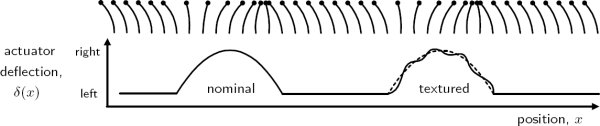
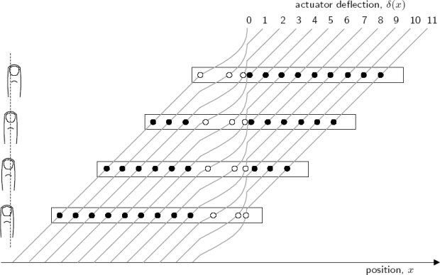
The deflection δi of each actuator i was a function of the slider position xs obtained from the encoder. The actuators followed the same deflection function δ(x), where x was the actuator position along the reading surface, as illustrated in Figure 7. The physical configuration of actuators introduced a spatial phase difference of ε. The first actuator was given a position corresponding to the slider position.
What we selected was a pattern (Footnote: Movies of the VBD in action can be found online on the Haptic Laboratory's VBD web page.) such that the deflection of each actuator swept the first half-cycle of a sinusoid, starting from the left position, as it scanned a virtual dot, as shown in Figure 7. A small-amplitude, high-frequency sinusoid could also be added to the nominal waveform to enhance contrast. These representations were termed nominal and textured.
These patterns were found to better approximate the sensation of scanning over Braille dots than others that were experimented with, such as triangular or square waves, full-cycle sinusoids, or textured blanks.
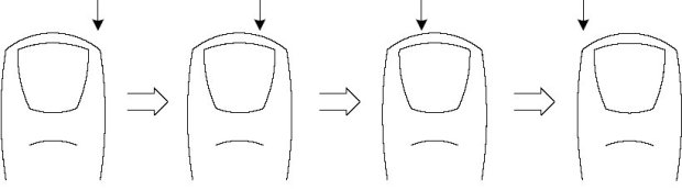
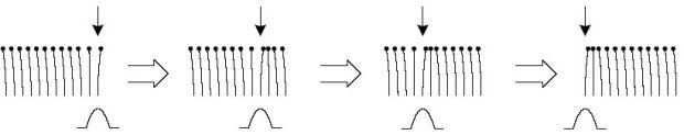
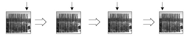
The spatial phase difference between actuators resulted in the representation of dots as a traveling wave. Figure 8 and 9 illustrate the movement of actuators as a virtual dot traverses the length of the display. Moving the slider in one direction across a region containing a dot resulted in a wave of actuator deflections traveling at the same speed in the opposite direction on the tactile display, causing the illusion that the reading finger was scanning over stationary Braille dots. Since the deflection function was independent of direction, it caused actuator deflections in the direction of finger movement when reading from left to right, but opposing movement when reading from right to left. The resulting sensations, however, seemed to be similar.
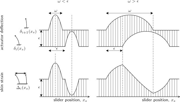
This pattern had two distinct effects on the skin deformation. The first was to cause a net displacement of a skin region around each contactor. The second was a pattern of compression and expansion of each small region of skin located between two contactors. Patterns of expansion and compression can actually be observed when a finger scans over small shapes [Levesque and Hayward 2003]. The strain variations Δi caused by a pair of actuators is represented in Figure 10. The width ω of a virtual dot is shown relative to the spatial period ε. If ω<ε, then there was no overlap between the deflections of adjacent actuators. If ω>ε, then an overlap existed and there was a continuous transition from expansion to compression. If ω>2ε expansion and compression never reached their maximum values. It is not known whether local displacement or local variations in strain, or both forms of stimulation, caused the illusion of the dot moving under the finger.
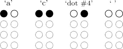
The tactile display could only display a single row of Braille dots. From the Braille character set, the three characters that have dots in row 1 only, or a total absence of dots, could be displayed: 'a', 'c', and ' ', see Figure 11. The fourth possible combination, unused in Braille, was called 'dot #4'.
(a)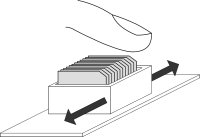
(b)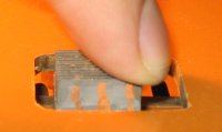
(c)
Figure 3: Interaction with the VBD: (a) strain applied during exploration, (b) illustration and (c) picture of finger contact with the VBD.
2.1.1 Tactile Display
2.1.2 Control System
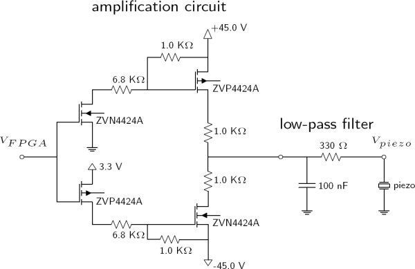
Figure 6: Electronic circuits: amplification circuit (left) and low-pass filter (right).
2.2 Skin Deformation Patterns

(1)